Alignment Points
This section describes how to use alignment points and alignment point areas.
An alignment point is the origin of the coordinate system used for the items inserted on the drawings. The location relative to the alignment point is used when exporting 3D-BIM elements or calculating distances between items.
Make sure you set a location for the alignment point that will be easy to locate on all of the floors of the building and that will not move during the course of the project. A corner of the building, a column, or the intersection of two architectural grids lines are all examples of good alignment point locations.
Multiple Alignment Points
A drawing can have more than one alignment point. The first alignment point inserted is used for all items on the drawing. Additional alignment points are inserted with boxes, called alignment point areas, around them. All items in the alignment point area are associated with the corresponding alignment point. Any items not inside an alignment point area are associated with the first alignment point.
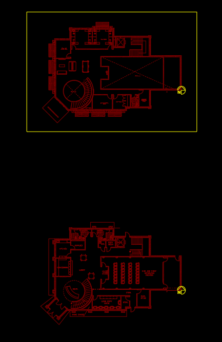
The following example shows a drawing file with multiple alignment point areas and floor plans. Notice how an alignment point area is drawn around the second alignment point.
Common Alignment Point Information
The values that can be specified for alignment points are listed below.
-
Alignment Point Area Name The name of the alignment point.
-
Floor The floor associated with the alignment point area.
-
Pipe Types ☰ The pipe types associated with the alignment point. For each pipe type and floor, there is one corresponding alignment point.
Once a pipe has been inserted in an alignment point area, that pipe type will be locked to that alignment point. That pipe type cannot be removed from the alignment point without first erasing the pipes in the area.
Commands
📄️ Insert Alignment Point
The Insert Alignment Point command is used to insert alignment points and alignment point areas on the drawing. Multiple alignment points can be inserted on a drawing.
📄️ Query Alignment Point Area
To query and edit an existing alignment point, go to
📄️ Move Alignment Point
The Move Alignment Point command can be used to move an alignment point on the drawing. You can also use AutoCAD commands to move the alignment point.
📄️ Rotate Alignment Point
The Rotate Alignment Point command can be used to rotate an alignment point on the drawing. You can also use AutoCAD commands to rotate the alignment point.
📄️ Offset Alignment Point for 3D Export
The Offset Alignment Point for 3D Export command can be used to specify the origin when exporting a drawing to 3D for collision detection. By default, the alignment point acts as the origin. Use this command if having the alignment point as the origin causes problems in the 3D export.
📄️ Remove Alignment Points from non-DM Drawing
The Remove Alignment Points from non-DM Drawing command is used to remove all alignment points from a drawing that does not use Design Master features. This command is the only way to fully remove alignment points from a drawing.