
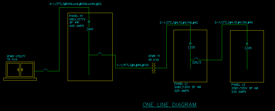
 One line diagrams are the first of the two premier features we included with Design Master Electrical 6.0 that we are going to discuss. Before we begin looking at how the feature works, take a moment to click on the picture to the right and see what the end result of this feature is.
The one line devices that we discussed in the last article are an important component of this feature. We included a lot of variety partly to allow you to define all of the pieces necessary on a one line diagram. Some devices that previously we ignored, because they did not affect the calculations we were doing, are now more important because they need to be represented. Connection between these various devices are establish as they were before. The command name has changed from Panel to Panel Connections to One Line Device Connections to reflect the new array of options, but it still works the same. Once the one line relationship between devices has been established, the real fun begins.
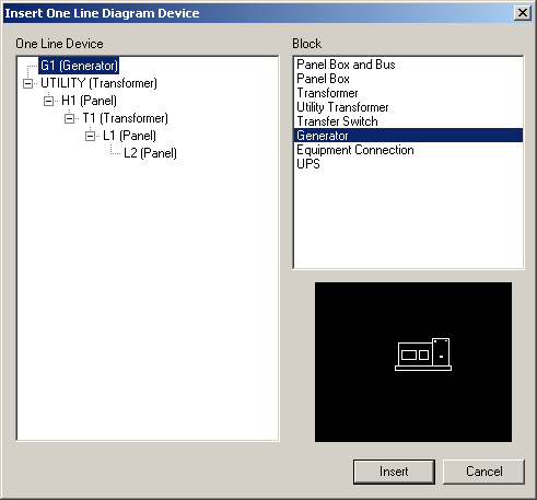 You start by inserting devices on the drawing. The insertion dialog has a list of one line devices and equipment connections on the left and a list of blocks on the right. Listing the equipment connections on the left allows you to insert large motor loads on the one line, such as elevators and air handlers, when necessary.
Before starting our implementation of this feature, we collected samples of one lines from our customers. We quickly learned that there is no such thing as a standard one line. As a result, we decided to make customization of the graphics a priority. All of the graphics are based upon block definitions. You can add, remove, and modify blocks in the list. The process is simple enough that if you discover in the middle of a project that you are missing a block that you need, you can take a quick moment, create it, and continue on with your design.
There are two special blocks that are included: Panel Box with Bus and Panel Box. Both of these include a resizable rectangle that represents the device. The with Bus block also includes the bus of the panel. The graphics of the bus are controlled by the definition of the panel. Some of the changes that we implemented to panels were done so that this could be properly drawn. The block used to represent the disconnect is matched to the disconnect type defined in the database. The blocks at the top and bottom of the bus used to represent the lugs are matched to the lug definition of the panel. A panel with standard lugs has a block at the top of the bus. A panel with feed through lugs has blocks at the top and the bottom of the bus. A panel with double lugs has a different block at the top of the bus. When the one line is updated, these graphics are checked against the current info in the database and any discrepancies are fixed. This quality control check insures that what you have on the one line diagram matches what you have specified on your panel schedule.
As you continue to insert one line devices, feeder wires between devices that are connected are inserted automatically. If the feeder has an over current protection (OCP) device on it, a block is inserted on the feeder for you. When updated, these blocks are added or removed as necessary. It is also possible to insert custom blocks on the ends of the feeder wires if your graphic standards require it. Like the blocks used to define devices, the blocks used on feeders are built to be easily customizable.
These wires are special entities make modifications easy for you. When the OCP is moved, it is restricted to staying on the feeder. When the device connected to the feeder moves, the end of the feeder is pulled with it. When the one line diagram is updated, all of the feeders between devices are checked. If the two connected devices are no longer connected to each other, the feeder is removed. If a new connection has been created, a new feeder is inserted on the diagram for you. After an update, the state of the one line diagram on the drawing will exactly match the state of the connections you have established between devices in the database.
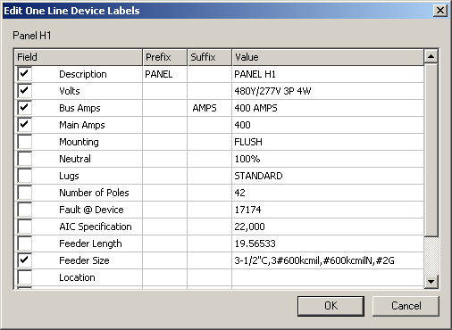 All devices and feeders can be labeled. The labels are grouped with the device, so that moving the device moves the label with it. The labels are linked to the database. A change in a panel definition is reflected automatically in the one line diagram. The dialog shown here shows the labels that are available for a panel. You can insert custom text both before and after the label to make it match your existing standards.
In our next article, we are going to start taking a look at our second premier feature: a link between the database and Excel.
Do you have feedback on this article? Let us know what you think!
©2001-2023, Design Master Software, Inc