Released August 27, 2012
The following is a list of new and updated features in Design Master HVAC 7.2. The requests from our public wish list are highlighted.
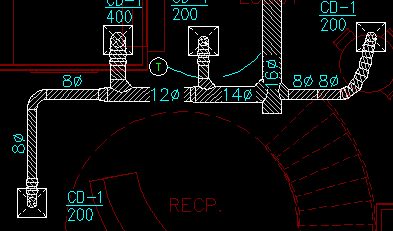
 Duct Hatching: The 2D ductwork can be hatched. The hatching settings are controlled by the layer system and duct type. (Requested on the wish list.)
Use the DM HVAC->Customization->Layers command and double-click on a layer system name to set the hatch settings for that layer system.
For each duct type, you can set whether or not it is hatched. You can choose whether or not to hatch flex duct. You can have the hatch extend past the edges of the ductwork.
If you need some ducts hatched, but others not hatched, use different layer systems. Set the hatching appropriate for each layer system, and adjust each duct to use the corresponding layer system.
Odd Duct Sizes: Duct smaller than a certain size can be sized to odd inches. You can set the option individually for each duct shape using the DM HVAC->Customization->Options, Ductwork->Use odd rectangular duct sizes below this size, Use odd round duct sizes below this size, and Use odd flat oval duct sizes below this size options. When ducts are sized, if they are below the size listed in the option, even and odd duct sizes will be used. Anything larger than the option will be sized to even inches. The default value for this option is 0, meaning that all ducts are sized to even inches. (Requested on the wish list).
Minimum Duct Sizes: A minimum size for ducts can be set using the DM HVAC->Customization->Options, Ductwork->Minimum duct size option. Ducts will not be sized any smaller than the size in the option. The default value for this option is 0, meaning there is no minimum duct size. (Requested on the wish list.)
Duct Hangers on Separate Layers: Separate layer keys for duct hangers in 2D and 3D were added, allowing hangers to be inserted on a different layer from the ductwork. (Requested on the wish list).
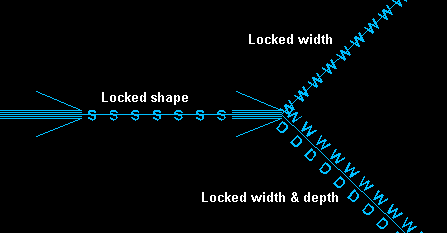
Duct Centerline Locking Feedback: Ducts that have their width, depth, or shape locked have their centerline graphics changed to indicate this on the drawing. The new centerline graphic makes it easier to see which ducts are being sized automatically and which are being sized manually.

Remove Pressure Drop Report Command: A command to remove a pressure drop report from the drawing and reset the color of the critical run has been added.
Break Vertical Ducts: The Break Duct command now works on vertical ducts. Breaking vertical ducts makes it easier to model vertical stacks of ductwork.
Improved Duct Insertion: The Inset Duct command was upgraded to work like the Insert Pipe command in Design Master Plumbing. While inserting ducts, you can use the Set info option to change the duct settings for the next duct you insert. When you connect a duct to a vertical duct, you can easily connect at any elevation, rather than just the top. A break in the vertical duct will be inserted if you connect the horizontal duct to the middle of the vertical duct.
Copy Room: You can now copy rooms on the drawing using standard AutoCAD commands. (Requested on the wish list.)
Zone Map: The zone that each room is in can be highlighted on the drawing using the DM HVAC->Building Definition->Zones->Insert Zone Map command. Using this command makes it easier to verify that the your rooms are grouped into appropriate zones. (Requested on the wish list.)

Variable Air Volume vs Constant Volume Systems: Zones can be specified as Variable Air Volume or Constant Volume systems. In VAV systems, the supply air required in the zone is based upon the coincident peak. In CV systems, the supply air required is the sum of the supply air required in each of the rooms in the zone.
Actual Supplied CFM in Ventilation Calculations: A new check box labeled Use Actual Supplied CFM in Ventilation and Psychrometric Calculations was added to the DM HVAC->Building Definition->Project Information command. (Requested on the wish list.)
When this box is not checked, the supply CFM values in the ventilation and psychrometric calculations will be calculated based upon the room heating and cooling loads. When this box is checked, the supply CFM values int he ventilation and psychrometric calculations will be based upon the airflow through the diffusers inserted on the drawing.
Typically, this box will not be checked when starting a project. The ventilation calculations will use the calculated supply airflow values, because no diffusers exist on the drawing. Later on, once this supply diffusers have been inserted in the rooms, you can check this box to use those airflow values to more accurately calculate the ventilation rates in the project.
Ventilation Percentage: A new check box labeled Maximum Room Ventilation Percentage was added to the DM HVAC->Building Definition->Project Information command.
When this box is not checked, the supply air required in a room will have a minimum value equal to the ventilation required in the room. If the heating and cooling loads for the room are low, you will end up with rooms that require 100% ventilation. If the ventilation rate in one room is 100%, the ASHRAE 62 and IMC calculations require the ventilation for the entire zone to be 100%.
When this box is checked, you specify a maximum ventilation percentage for rooms. The supply air minimum value will be set to maintain this maximum percentage. Using this option makes it easier to keep ventilation rates in all of your rooms at reasonable values and prevent an entire zone from requiring 100% ventilation.
Export Flex Ducts: You can choose whether or not to inlude flex ducts when exporting your HVAC model to an IFC file. (Requested on the wish list.)
Export Diffusers: You can choose whether or not to inlude ceiling diffusers when exporting your HVAC model to an IFC file.
Import Multiple Master Schedule Entries: You can import multiple entries from the master diffuser schedule to the project schedule at one time, rather than having to import each entry individually. (Requested on the wish list.)
Zoom to Schedule: When a schedule is inserted, a Zoom to Schedule After Insertion checkbox is included when inserting a schedule. If this box is checked and the schedule is already inserted on the drawing, you will be moved to the location of the schedule on the drawing. Never lose a schedule on a busy drawing again!
Schedule Column Justification: Each column in a schedule can have its justification individually set to left, center, or right. Previously, all columns were left-justified. To change the column justification, press the Edit Title, Column Labels, and Column Order button when inserting the schedule.
Schedule Title and Column Label Justification: The justification of schedule titles and schedule column labels can be set using the Options command. Go to DM HVAC->Options->Customization and look for the Schedule title justification and Schedule column label justification entries in the Miscellaneous section. The justification can be set to left or center.
Merge Project: Drawings from one project can be merged into another project. (Requested on the wish list.)
Copy or Backup Project: The new Copy of Backup Project command can be used to make a complete copy or backup of the current project. When you copy or backup a project, it is important to copy all of the drawings and the DM database files. This command will take care of copying all the files necessary. Use this command if you want to make a backup of the current state of the project or if you want to make a copy to try a different design idea on.
Copy Drawing and Remove Links to Database: The new Copy Drawing and Remove Links to Database command will copy the current drawing, remove all the links between the DM entities on the drawing and the database, but will not remove any of the DM entities. The copied drawing will look exactly like the original, but will not have any DM intelligence included with it. You can then use standard AutoCAD drafting commands to modify the drawing.
Rename Database: The Rename Database command will change the name of the database file associated with the current drawing. It will change the suffix of the file when viewed in Windows Explorer. Nothing else in the project will be changed.