
The load calculations in Design Master HVAC 5.0 underwent a major revision. This page describes the changes we made to help you model more complex buildings.
We added a brand-new feature that we call load maps. It is an experimental concept to help you visualize the load defined in your project. You can read about load maps and how they can help you with your design in the Load Maps article.
You can read about the other non-load changes in the Design Master HVAC 5.0 article.
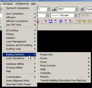
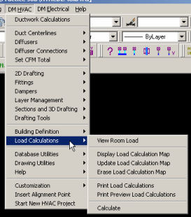
The first change you will notice is that the DM Building pulldown menu has been removed. All of the load calculation commands can be found under DM HVAC->Building Definition and DM HVAC->Load Calculations.
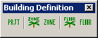
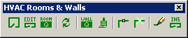
There are a number of new toolbars that you can use instead of the pulldown menu.
The Building Definition toolbar has commands for modifying the project, zone, and floor settings.
The HVAC Rooms & Walls toolbar has commands for editing room definitionsin the database and outlines on the drawing.
The Load Calculations toolbar has command for viewing and printing the loads, including the new load maps.

|
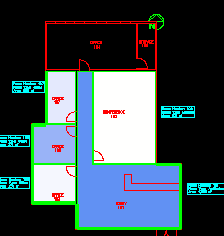 |
| A load map |
The changes in this section relate to the information you provide to define the building model.
All rooms in a project are linked to a specific room type in the schedule. When first created, all room settings are inherited from the room type. If the room type is redefined, the rooms linked to it are redefined also. Settings can be overriden in specific rooms if necessary.
Rooms can be renamed (and it's about time!).
Rooms can be excluded from either the heating or cooling calculation.
Two ventilation criteria can be set for a room. This allows room to meet ASHRAE 62, which specifies both ventilation based upon both the area and occupancy of a room.
The infiltration into a room can be based upon CFM / sf of wall.
The ventilation and infiltration values can be set differently in the heating and cooling calculations.
A minimum supply air value can be set in a room.
A room schedule that has ventilation numbers set to match ASHRAE 62.1-2004 can be downloaded. These room definitions will allow you to satisfy the ventilation requirements for specific rooms.
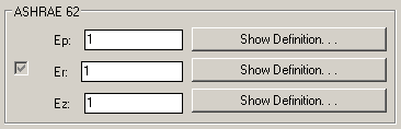
The ventilation required in zones can be calculated using ASHRAE 62. These values end up being higher than what Design Master would normally calculate. The calculation requires that you specify Ep, Er, and Ez in the Zone dialog. The definition of these values can be found in Appendix A of ASHRAE 62.1-2004.
Pyschrometric can be calculated for each zone. The AHU and Coil Settings and Duct Settings in the Zone dialog were added for this calculation.
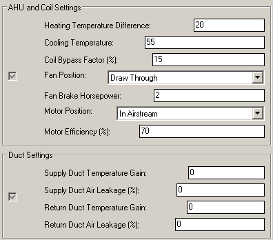
In the pyschrometric output, the humidifcation or reheat required for the system is displayed.
The indoor air default values have been moved out of the project setting and into the zones. This includes the heating temperature, cooling temperature, and relative humidity values.
The design conditions for cities can be customized. Temperatures for existing cities can be modified. Cities can be renamed or removed. New cities can be added.
A separate ventilation safety factor has been added.
 Zones are much improved in this release. Previously, you were limited to a Project->Zone->Room hierarchy. Now, you can have zones underneath other zones, giving you a Project->Zone->...->Zone->Room hierarchy.
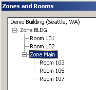
There is a new Zones and Rooms dialog that has a tree view of the zones and rooms in the project. You can drag-and-drop zones and rooms around like you do folders in Windows Explorer.
The outside air wet bulb temperature can be tempered.
A zone can be defined as having a plenum return. In this configuration, the roof, and part of the lighting and wall loads are all removed from the room load and seen only in the system load.
The number of people in a zone can be diversified.
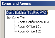
In the project shown above, there is a single zone with three rooms in it. The load in each of the offices is based upon one person. The load in the conference room is based upon two people.
However, we know that there will never be more than two people in the space, either in their office or the conference room. The people diversity in the zone is set to two to model this situation.
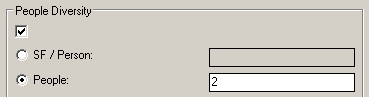
As a result, the total people load in the zone is lower than the sum of the people loads in the three rooms that are in it.
A second wall type on the lower portion of a wall can be defined.
Glass shading based upon overhangs and fins can be properly calculated. This calculation requires that the dimensions be provided for the window, overhang, and fins.
Walls can have multiple types of glass defined.
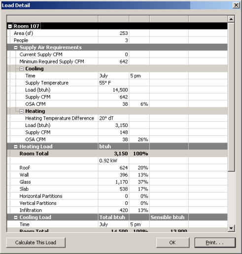
There is a new Load Detail dialog. It replaces the old Load Calculation Dialog that docked on the side of your screen. The new dialog is used to display the load of specific rooms and zone. You can view the dialog by using the View Room Load command and by pressing the View Load button on the Zone Tree dialog.
The dialog lists all of the heating and cooling load details from before. It also includes the area and number of people in the room or zone.
At the bottom-right, there is a Print button that can be used to print the current load exactly as it appears in the dialog.
There is an option to turn the page break after each section of the load print-out on or off.
In the Project Information section of the print-out, the time and date of the last calculation is display.
©2001-2023, Design Master Software, Inc